- GD&T is an international language used to describe a part accurately.
- It comprises symbols, rules, and definitions for defining the geometry of a mechanical part.
- It has many benefits like uniformity in drawings, better designs, no assumptions, and large tolerances.
- It is used especially in the manufacturing sector for dimensioning and tolerancing.
- The standard used was ASME Y14.5M-1994, and now ASME Y14.5-2009 is used.
- ASME Y14.5M-2018 (Current Standard)
American Society of Mechanical Engineers
In this article, we’ll dive deep into the fundamentals of GD&T, its benefits, symbols, and practical applications in manufacturing and design.
Why is GD&T Important?
In modern manufacturing, consistency and precision are critical. GD&T ensures that every component of a product meets the desired specifications, even when produced in different locations or by different manufacturers. It bridges the gap between design and production, ensuring:
- Improved Communication: Engineers, machinists, and quality inspectors can all interpret drawings consistently.
- Higher Quality: Defining tolerances precisely minimizes errors.
- Cost Efficiency: Reduces material waste and machining time by eliminating unnecessary tight tolerances.
Key Elements of GD&T
GD&T consists of a set of symbols, terms, and rules that define the allowable variations in a part’s geometry. These elements are broadly categorized into:
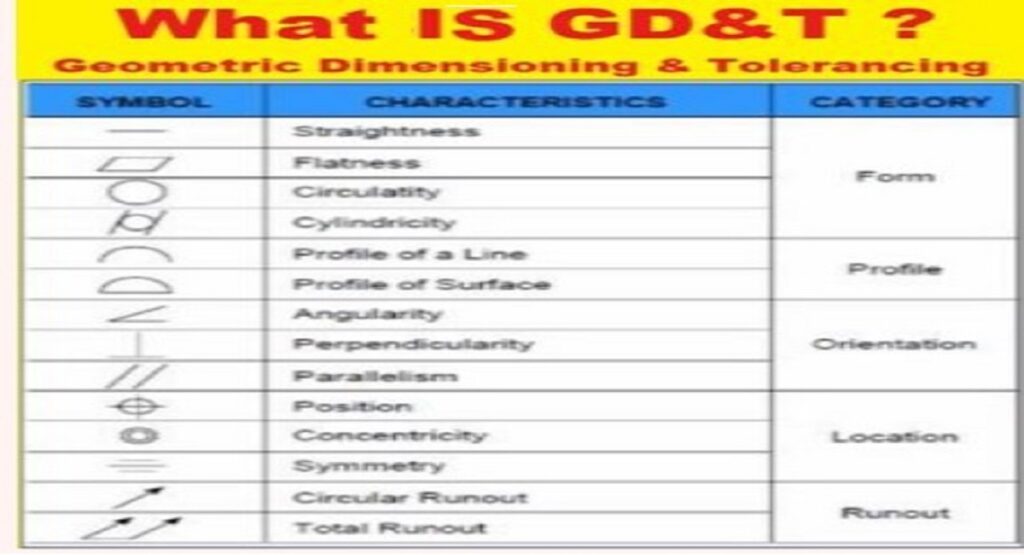
1. Symbols and Characteristics
GD&T uses a range of symbols to specify tolerances. These symbols are divided into two categories:
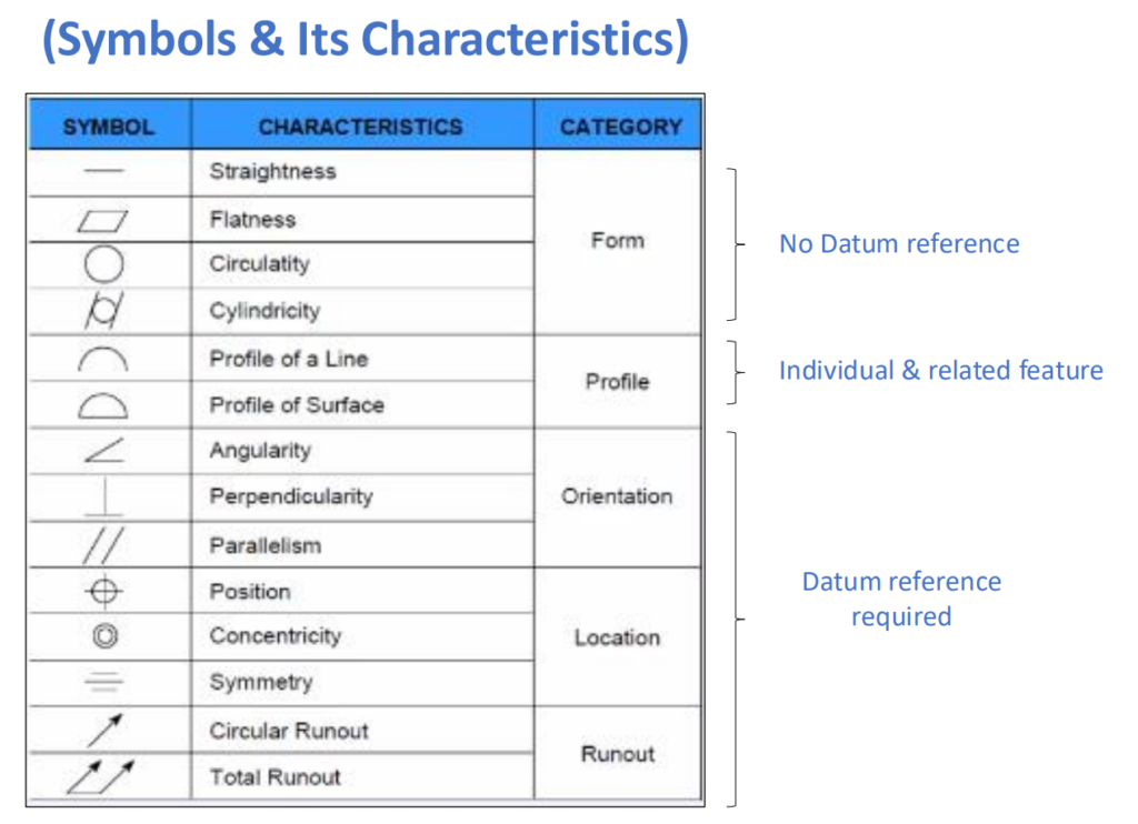
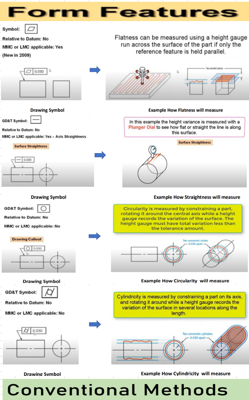
- Form Tolerances (No Datum Reference Required):
- Flatness: Ensures a surface is flat within the specified tolerance.
- Straightness: Controls the straightness of a line or axis.
- Circularity (Roundness): Ensures circular features are within the tolerance zone.
- Cylindricity: Applies to cylindrical parts, ensuring uniformity along the entire surface.
- Orientation, Location, and Runout Tolerances (Datum Reference Required):
- Perpendicularity : Ensures a surface or axis is at a right angle to a datum plane or axis.
- Angularity: Controls the angle of a surface or feature relative to a datum.
- Parallelism: Ensures two surfaces or axes are equidistant.
- Position: Defines the exact location of features like holes or slots.
- Concentricity & Symmetry: Controls the alignment of features relative to a central axis or plane.
- Runout (Total Runout): Controls the surface variation when a part is rotated around its axis.
2. Datums
Datums serve as reference points or planes for measuring tolerances. They are crucial for aligning and inspecting parts.
3. Feature Control Frames
Feature Control Frames are the rectangular boxes containing GD&T symbols, tolerance values, and datums. They provide all the necessary information for applying a specific tolerance.
How GD&T is Measured
Conventional Methods
Many GD&T characteristics can be measured using traditional tools such as:
- Height Gauges and Surface Plates: For flatness and straightness.
- Dial Indicators: For runout and parallelism.
- Profile Projectors: For angularity and other complex features.
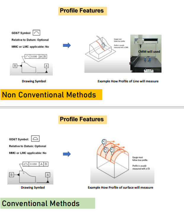
Advanced Methods
Modern manufacturing often employs Coordinate Measuring Machines (CMMs) for precise and automated inspection of GD&T tolerances, particularly for:
- Profile of Line and Surface
- Concentricity and Symmetry
- Position tolerances
Practical Applications of GD&T
GD&T is widely used across industries, particularly in aerospace, automotive, and manufacturing sectors. Here’s how it impacts each stage of production:
- Design: Engineers can clearly specify functional requirements without over-constraining the design.
- Machining: Machinists understand which tolerances are critical and prioritize their processes accordingly.
- Inspection: Quality inspectors use GD&T to verify that parts meet design specifications, ensuring compatibility and performance.
Benefits of GD&T in Manufacturing
- Enhanced Fit and Functionality: It ensures that parts fit together seamlessly, even when made by different vendors.
- Global Standardization: The ASME Y14.5M standard makes it easier for companies worldwide to collaborate.
- Cost Savings: By focusing tolerances only on critical features, GD&T reduces unnecessary expenses.
- Quality Control: GD&T promotes a systematic approach to inspection, minimizing defects and rework.
Common Challenges
Despite its benefits, it can be challenging for newcomers due to its complexity. Here are a few common hurdles:
- Lack of Training: Understanding and applying GD&T requires training and practice.
- Over-Application: Using GD&T unnecessarily can complicate manufacturing and increase costs.
- Inspection Limitations: Not all companies have access to advanced inspection tools like CMMs.
Fortunately, most GD&T tolerances can still be measured using conventional methods, ensuring accessibility even for smaller manufacturers.
Conclusion
Geometric Dimensioning and Tolerancing is a cornerstone of precision engineering. By defining tolerances clearly and unambiguously, it facilitates better communication, higher quality, and cost-effective manufacturing.
Whether you’re an engineer, machinist, or quality inspector, mastering GD&T is essential for success in the modern industrial landscape.
Start by familiarizing yourself with its symbols, rules, and applications, and don’t hesitate to seek expert training to enhance your skills. GD&T is more than a set of rules; it’s the language of quality and precision in manufacturing.
Click Here For Similar Articles:
- Top 15 MNCs Every Mechanical Engineer Dreams of Joining in 2025

- How to Digitize and Automate the CAPA Process

- Top 10 Essential Tools Every Mechanical Engineer Should Know

- What is GD&T (Geometric Dimensioning & Tolerancing) ?

- Principles of IATF 16949: A Guide to Quality Management

- The Evolution of IATF 16949: The Automotive Quality Standard

- Top Interview Questions Related to SPC ,Cp and Cpk

- Difference Between Purchase and Procurement

- Master Your Job Interview: Top 70 Common Interview Questions and Answers

- What Is Standard Deviation ?

- Top Interview Questions and Answers on SPC
- Top 20 Interview Questions For Customer Quality Manager ?